μCOM-87: The Strangest Architecture You've Never Worked With
With most of the DX7's technical mysteries laid bare (for now), I've had some free time to poke around inside another 80s digital synth icon: the Casio CZ-101.
In 1983, Yamaha changed the music world forever with the release of the DX7. It used a new synthesis technique called FM synthesis to create a bold, futuristic sound that was radically different from everything else available. It wasn't just a commercial success; The DX7 was a tectonic shift that reshaped the entire landscape of popular music, and left Yamaha's competitors scrambling to get in on the action. The theory behind FM synthesis was simple, but Yamaha held the patent and were fiercely protective of their advantage. It would take Korg and Roland years to bring their own competitors to market, but Casio —a comparatively small player in the synth market— managed to thread the needle with the CZ-101's Phase Distortion Synthesis. If you closed your eyes you could almost pretend someone had shrunk a DX7. It had plucky basses, resonant bells, gritty metallic percussion... All without running afoul of the notoriously litigious Yamaha's FM patents. The CZ-101 was a lot of fun squeezed into a small package. It sold well, and still enjoys a cult status today.
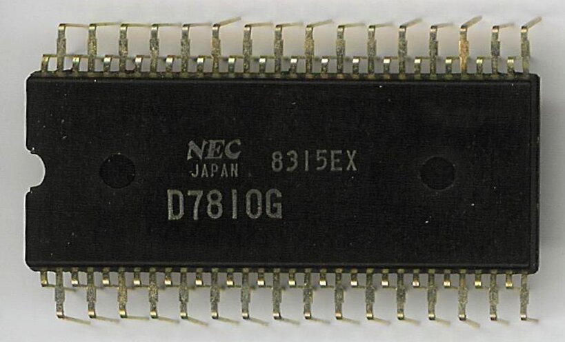
Under the hood, the CZ-101 uses several NEC chips: The proprietary μPD933 tone generator 1, and the μPD7811G microcontroller. Unsurprisingly, no public documentation exists for the μPD933, and —despite having once been a commercial product— the situation for the μPD7811G isn't much better. When I started poking around in the firmware ROM, I struggled to find good resources online about the μCOM-87 architecture used in the μPD7811G... Despite appearing in some really important places there's surprisingly little written about it online. For that reason I decided to write my own account of its more baroque features.
Background #
In 1978 Japanese mega-corporation NEC 2 launched their first original 8-bit processor architecture: The μCOM-87. Until this point, NEC's 8-bit architectures had all been based on existing designs, such as the Intel 8080-compatible μCOM-8, and Zilog Z80-compatible μCOM-82.
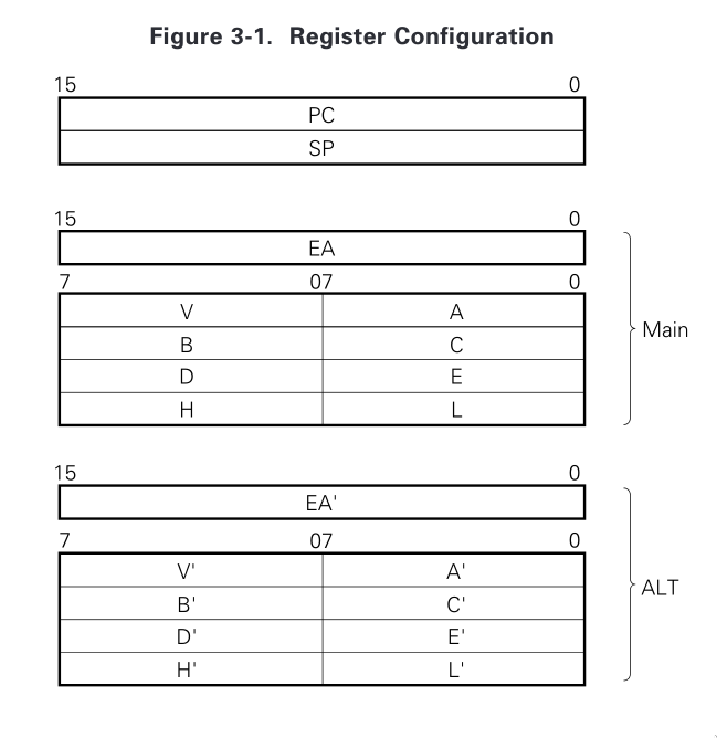
NEC had clearly learned a few things from their American counterparts: The μCOM-87 architecture featured two parallel banks of 8080-like registers, which could be swapped between like in the similar Z80. The 8-bit B and C registers can also be 'paired' into a single 16-bit register (BC). Same with DE, and HL, similar to the 8080 and Z80 architectures.
Now I know what you're thinking: Yeah, yeah. 8080-compatible registers, register pairing, alternate banks... This is all pretty normal 8-bit stuff. Sure... But those are just about the only normal things about the μCOM-87 architecture. Let's take a look at a few of its more exotic features...
Instruction Skipping #
0ABCDh, rather than 0xABCD.
Instead of conventional comparing and branching instructions, control flow on the μCOM-87 works by conditionally skipping instructions.
; Read a byte from the serial interface into A.
; Clamp the value between 0xA - 0xF, then send back.
    MOV         A,RXB

; Skip the next instruction if A < 0x10.
    LTI         A,010h
; Clamp A at 0xF.
    MVI         A,0Fh

; Skip the next instruction if A > 0xA.
    GTI         A,0Ah
; Clamp A at 0xA.
    MVI         A,0Ah

    MOV         TXB,A
The above example reads a value from the serial interface, and clamps it between 0xA and 0xF. The LTI (Less Than
Immediate) instruction skips the next instruction if the register is less than the immediate operand. Similarly, the GTI instruction skips if the
register is higher than the immediate operand.
Instruction skipping is practically unheard of in modern architectures, but featured in a few other historic ones like the PDP-8, and Microchip's PIC architectures prior to PIC18.
The following table lists most of the μCOM-87's instructions which can trigger the next instruction to be skipped. Some nearly identical instructions have been omitted for brevity 3.
| Instruction | Description | Skip Condition |
|---|---|---|
| ADDNC r, A | Add A to Register. Skip if No Carry | No carry generated |
| ADDNCX rpa | Add Memory addressed by Register Pair to A. Skip if No Carry | No carry generated |
| BIT bit, wa | Bit Test Working Register | V.wa[bit] != 0 |
| DADDNC EA, rp3 | Add Register Pair to EA. Skip if no Carry | No carry generated |
| DEQ EA, rp3 | Equal Register Pair with EA | EA == rp3 |
| DGT EA, rp3 | Greater Than Register Pair | EA > rp3 |
| EQA A, r | Equal Register with A | A == r |
| EQAW wa | Equal Working Register with A | A == (V.wa) |
| EQI r, byte | Equal Immediate with Register | r == byte |
| EQIW wa, byte | Equal Immediate with Working Register | (V.wa) == byte |
| GTI r, byte | Greater Than Immediate | r > byte |
| GTIW wa, byte | Greater Than Immediate | (V.wa) > byte |
| LTI r, byte | Less Than Immediate | r < byte |
| NEA A, r | Not Equal Register with A | A ≠ r |
| NEAW wa | Not Equal Working Register with A | A ≠ (V.wa) |
| NEI r, byte | Not Equal Immediate with Register | r ≠ byte |
| NEIW wa, byte | Not Equal Immediate with Working Register | (V.wa) ≠ byte |
| OFFI r, byte | Off-Test Immediate with Register | A & byte == 0 |
| OFFIW wa, byte | Off-Test Immediate with Working Register | (V.wa) & byte == 0 |
| ONAX rpa | On-Test Memory addressed by Register Pair with A | A & rpa != 0 |
| ONI r, byte | On-Test Immediate with Register | r & byte != 0 |
| ONIW wa, byte | On-Test Immediate with Working Register | A & (V.wa) != 0 |
| SK f | Skip if Flag | f == 1 |
| SKN f | Skip if No Flag | f == 0 |
| SKIT irf | Skip if Interrupt | irf == 1 |
| SKNIT irf | Skip if No Interrupt | irf == 0 |
| SUINB r, byte | Subtract Immediate from Register. Skip if No Borrow | No borrow generated |
| SUBNB r, A | Subtract A from Register. Skip if No Borrow | No borrow generated |
Instruction Stacking #
If multiple MVI (Move Immediate to Register) instructions with the same destination register are placed sequentially, only the first instruction will actually be executed. The rest will be processed as NOP operations (however the equivalent number of CPU cycles will still be used). The μCOM-87 architecture literature refers to this as 'instruction stacking'.
The following example takes advantage of instruction stacking to create a table of values to load into the A register, and send over the serial interface.
; Read a byte from the serial interface, and send a byte based on its contents.
    MOV         A,RXB

    NEI         A,1           ; Skip if A ≠ 1.
    JR          received_1

    NEI         A,2           ; Skip if A ≠ 2.
    JR          received_2

; Received any value other than 1 or 2.
    MVI         A,0Ah
received_1:
    MVI         A,0Bh
received_2:
    MVI         A,0Ch

    MOV         TXB,A
Because the stacked MVI instructions aren't executed, there's no need to jump to the final MOV instruction. By not needing any branching instructions this saves a few extra bytes, at the expense of a few processor cycles.
Working Vector Register #
The μCOM-87 architecture features an index register mechanism similar to the Direct Page register in Motorola's 6809 architecture. The Working register vector register (V) allows a programmer to specify a base address, to which an immediate 1 byte offset is added to create a 16-bit address operand for certain instructions, rather than needing the full 2 bytes.
Consider the following example: Setting the V register to 0x40 lets us access the addresses 0x4000 to 0x40FF with only a single byte.
; Loads the byte at 0x4001, decrements it, and stores it at 0x4001 again.
; Total bytes = 9
    MOV         A,(4001h)
    DCR         A
    MOV         A,(4001h)


; Sets the vector pointer, then decrements the byte at 0x4000 + 0x1.
; Total bytes = 4
    MOV         V,40h
    DCRW        1
Most instructions have a working register equivalent, such as the DCR, and DCRW instructions shown in the example above.
Call Table #
The μCOM-87 architecture has a vector table of 32 user-defined function pointers (at address 0x80), which can be called with the single byte
CALT instruction, reducing the amount of bytes needed to encode a common function call. E.g., CALT 5 will store the return pointer on
the stack, and jump to the function pointer at index 5 (0x80 + (5*2)) in the call table. Like many other μCOM-87 features, it prioritises code
density over other concerns.
Working With μCOM-87 Today #
Unfortunately there aren't a lot of tools available for working with the μCOM-87 architecture today. For assembling programs I use Alfred Arnold's Macro Assembler AS, which is probably the best option available. Unfortunately I haven't been able to track down a copy of NEC's own RA87 Relocatable Assembler, mentioned in their official technical literature. A version for MS-DOS was available, which could be run in an emulator if a copy was found.
For disassembling programs, I was fortunate that Github user depili had already put in the hard yards creating a Ghidra processor specification. I've picked up the torch with this Pull Request on the Ghidra project github, which is still open as of December 2025. Alternatively, there's MAME's Unidasm, and a few other bespoke disassemblers like dasm7810, or Nec78CDasm.
The best official reference material I've found for working with the μCOM-87 architecture is the μPD78C18 datasheet (A later member of the μCOM-87 family). It's available from Renesas Electronics, who took over NEC's semiconductor business in 2010.
The upd781x-series are emulated in MAME, so it's possible to build an emulator for debugging. The brilliant Devin Acker took advantage of this to build an amazing CZ-101 driver!
The information in this article was pieced together from a variety of odd sources. This page, in Japanese, was a huge help when I first started looking at the architecture. The MAME source code also provided a few helpful hints, like where to look for a modern datasheet. If you have any pointers, or helpful hints of your own, please get in touch!
- The μPD933 went on to appear in the rest of Casio's CZ line of synthesizers, and other 'non-synthesizer' products, such as the Casiotone CT-5000. ↲
-
By 1985 NEC had the highest annual revenue of any semiconductor company, a position it would retain amidst stiff competition until being overtaken in 1992 by Intel, who have held the title ever since. (Dataquest Incorporated. (1994). Semiconductors Core Binder, 483. [Link])
Over time the semiconductor industry shifted towards American suppliers like Intel/Motorola, as the previously unstoppable Japanese economy began to decline, and the Japanese industry's less risk-averse Silicon Valley counterparts made great advances in processor design. ↲
- The μCOM-87's instruction set has a lot of near-identical instructions, with different versions operating only on the A register, such as OFFI A, byte and OFFI r, byte. The variations of these instructions for the A register require less bytes to encode, and less CPU cycles to execute. ↲