How the Yamaha FM Synth Cassette Interface Works
Prior to the personal computer becoming the centrepiece of home music production, backing up and storing synthesiser patches was a non-trivial problem. Synth manufacturers experimented with various interesting methods over the years, however none of these has aged more poorly than digital cassette storage.
This article discusses the particular technical implementation of the data cassette interface used in Yamaha's FM synthesisers, and the historical context in which it was developed.
Background #
The years leading up to the DX7's groundbreaking 1983 release were a period of rapid, exciting innovation. The digital revolution had kicked into high gear, and technology was rapidly reshaping the world. The personal computer was on the verge of going mainstream, and the now ubiquitous 3.5"1 floppy disk was just beginning to appear in consumer devices. Electronic music production was about to take the world by storm, and the Ensoniq Mirage —which would bring affordable disk-based sampling to the masses— was only a year away2.
Despite the rapid pace technology was advancing, disk drives were still complicated, expensive devices. Putting a disk drive into a synth required lots of extra circuitry, driving up costs and introducing new modes of failure. Considering this, it's not surprising that synth manufacturers opted for cheaper alternatives3.
Fortunately, the home computing world had already found a cheap and reliable solution for data storage: Compact audio cassette tape. It's unclear where exactly this innovation originated, but by the late-1970s the use of cassette interfaces in home computers had become commonplace; with the first IBM PC —released in 1981— featuring one. It shouldn't come as much of a surprise then, that as synthesisers started to become digital devices they would opt for the same solutions. Many of the flagship synths of the 80s' would feature cassette interfaces, such as the Oberheim OB-X, Sequential Circuits Prophet 5, and the Roland Jupiter 8.
The DX9, released together with the DX7 in 1983, would be the first of Yamaha's FM synthesisers to feature a cassette interface4. This interface consisted of three 1/8" cable sockets to connect to the headphone, microphone, and remote sockets of a consumer-grade cassette recorder. Later synths in Yamaha's FM line —such as 1989's TX81Z— would use an 8-pin DIN socket for the cassette interface, coupled with a proprietary cable terminating in three 1/8" jacks; This 8-pin DIN socket format was shared with the MSX computer cassette interface, which is not surprising given Yamaha's involvement in its development.
The ability to distribute patches over an electronic medium opened up new possibilities for talented programmers: In the wake of the DX7, a new market emerged for patches for Yamaha's notoriously hard to program FM synths; with companies selling their patches on cartridges and cassette tape.
Protecting this new form of intellectual property was serious business, with professional DX7 patch authors reportedly going so far as embedding garbage information in their patch data to identify patch thieves after the fact, such as unique key scaling in unused operators, or invalid ASCII characters in a patch name5 (Cox & Warner, 2017).
While the glory days of the bands featured in voicecrystal.com's artist gallery may be behind them, their testimonials speak to the enormous impact that professional patch programmers had on the entire music industry.
Encoding Format #
The encoding scheme used by the Yamaha FM synthesisers' cassette interface is a variation of the 'Kansas City standard' format, known as CUTS. This format uses 'frequency shift keying' to encode digital data. The CUTS format is shared with MSX computers, and allows for higher speed data transfer than the standard Kansas City Standard format, allowing for a much faster 1200 baud6, as well as the original 300.
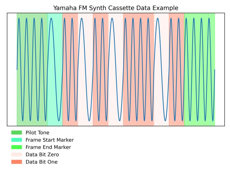
The audio signal begins with an extended 2400Hz 'pilot tone', which can be used to calibrate the volume of the input source. What follows is a sequence of data frames, each containing a single byte. Multiple data items (such as multiple patches, performances, etc) can be encoded in a single recording, separated by arbitrary lengths of the pilot tone.
A binary '1' bit (known as a 'mark') is encoded with two 'cycles' at 2400Hz. A '0' (known as a 'space') is encoded as a single cycle at 1200hz. A data packet, occupying roughly 9.1 milliseconds of tape, consists of a leading zero bit indicating the start of a data frame, followed by the actual 8 data bits, LSB first. Two trailing 'ones' indicate the end of the data frame.
The following diagram demonstrates the structure of an encoded data packet, the byte 0b10110101:
Implementation #
The technical implementation of the cassette interface in Yamaha's FM synthesisers is surprisingly simple: The raw electrical audio signal played from the cassette can be interpreted as binary data by the CPU's I/O ports, without requiring any analog to digital conversion. Sampling the positive peak of the audio wave period from the I/O port will be perceived by the CPU as a binary one, with a sample of negative voltage perceived as a zero.
Similarly, pulling an output I/O port's signal high, and low in quick succession will be recorded as a sinusoidal oscillation when sampled as audio by a tape recorder. By controlling the frequency of toggling the output voltage in the software, it is possible to create the encoded data output directly from the CPU, without requiring any additional, specialised circuitry.
By periodically sampling the I/O pin connected to the cassette interface's input port, it's possible to determine the frequency of the incoming audio by counting the number of times the polarity of the signal changes within an arbitrary period.
To accomplish this the synth firmware samples the cassette input I/O port at a set interval corresponding to the baud rate. The firmware controls this interval using an arbitrary delay routine, called between each sampling of the input port. Each successive sample is tested against the last using a XOR instruction, incrementing the 'polarity change count' if the values differ. The number of polarity changes within a period will indicate whether the period's frequency was 2400hz indicating a '1' bit, or 1200hz for '0'. From this information it is possible to construct the full byte.
The Yamaha FM synths use an interesting trick to construct the final value using the Hitachi HD6303 architecture's logical rotate instructions: Given that the number of polarity changes
counted in a period will either be less than two in the case of a '0' bit, or more than two in the case of a '1' (binary 0b10, or above), if the resulting pulse count is
logically rotated twice rightwards the processor's carry flag will be set in the case that the input value is a '1'. With the result of the last bit read stored in the processor's carry
flag, the result is then rotated rightwards into the most-significant bit of the result byte. Since each byte is encoded LSB first, after 8 iterations of this routine the final result byte
will have been decoded. This same method of constructing the final byte is used in the cassette interface code in the DX9, DX100, and TX81Z firmware, with only minor variations.
References #
- Cox, C., & Warner, D. (2017). Audio culture readings in modern music. New York Bloomsbury Academic.
- Yamaha DX100 Service Manual
- According to legend, its predecessor —the 5.25" floppy disk— was designed this particular size to discourage users from transporting them in their pockets, and subsequently damaging them by bending. ↲
- Ensoniq certainly deserves some credit for putting a 3.5" disk drive into their groundbreaking sampler: The Mirage was one of the first mass-produced consumer devices to incorporate this new standard for floppy disks. In fact, the first manufactured Mirage models apparently featured one of the first production 3.5" disk drives: The Shugart SA300. ↲
- History would ultimately vindicate this decision. A roaring trade of replacement disk drives for vintage synths exists on Ebay, Reverb, and other trading sites. The various encoding schemes used for these disks haven't stood the test of time either. While proprietary cartridges for vintage synths might not be easy to come by, the technology remains as reliable as it ever was. ↲
- It's hard to say why Yamaha opted for a cassette interface over the voice cartridge system featured in the DX7. Yamaha clearly didn't consider either medium technically superior to the other. Both were used in their subsequent DX/TX series synthesisers. The DX7II, and TX802 —released in 1986, and 1987 respectively— would both feature a cartridge interface, whereas every other would have a cassette interface. ↲
-
Having disassembled the firmware, and annotated all of the string subroutines, I can confirm that you could
safely do this. Invalid ASCII characters at the end of a patch name simply won't be printed. If an ASCII character value outside of the valid
0-0x7Frange is encountered, the string copy process will stop harmlessly. ↲ - The DX100 service manual helpfully confirms that the baud rate is indeed 1200. Yamaha's service manuals never disappoint: They remain a font of oddly-specific, however generally vague technical trivia. ↲